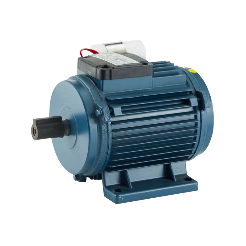
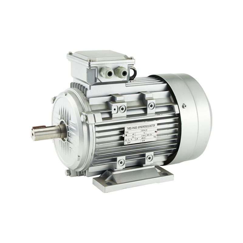
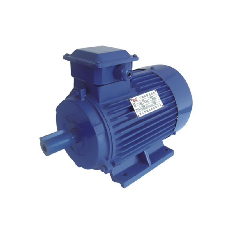
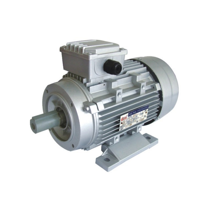
Rising demand for energy-saving drive systems has pushed more factories toward inverter-controlled motors. A modern production line may combine a High Efficiency Induction Motor with advanced VFD control to reduce power consumption, improve torque stability, and optimize speed regulation. Meanwhile, many compact automation systems still rely on a Universal Induction Motor architecture for flexible industrial applications. Despite these advantages, engineers frequently encounter one overlooked issue: bearing damage caused by variable frequency drives.
Our company has seen numerous cases where motors achieved strong electrical performance yet failed prematurely due to electrical bearing erosion. Proper understanding of shaft voltage, PWM waveforms, and grounding methods plays a major role in extending motor service life.
Why Bearing Damage Happens in VFD Systems
Traditional direct-on-line motors receive sinusoidal voltage from the power grid. A VFD, however, produces high-frequency pulse-width modulation (PWM) signals through rapid switching of IGBT modules.
Those switching pulses generate:
- Common-mode voltage
- High dv/dt spikes
- Shaft-induced current
- Capacitive coupling between rotor and stator
Electrical current searches for the lowest resistance path toward ground. Motor bearings often become that path.
Research from industrial drive specialists shows shaft voltage can exceed 70V peak-to-peak under certain operating conditions. Electrical discharge then penetrates the lubricant film inside the bearing race, creating microscopic craters. Over time, repeated discharges lead to frosting, pitting, fluting, vibration, and eventual bearing failure.
Common Symptoms of VFD Bearing Failure
Maintenance teams usually discover the problem through mechanical symptoms rather than electrical testing.
Typical warning signs include:
- Unusual bearing noise
- Increased motor vibration
- Excessive operating temperature
- Grease discoloration
- Audible high-frequency whining
- Premature bearing replacement cycles
Our company often recommends vibration analysis once bearing frequencies begin showing harmonic patterns around the outer race or inner race defect frequencies.
A damaged bearing surface may develop “fluting,” which appears as evenly spaced grooves along the raceway. This pattern is highly associated with inverter-driven motors.
Motor Sizes Facing Higher Risk
Not every motor experiences severe shaft current damage. Several factors increase the probability:
Large Frame Motors
Motors above 30 kW generally face greater common-mode voltage accumulation because of larger shaft surface areas and increased capacitance.
Long Cable Installations
Motor cable lengths above 15–20 meters can amplify reflected wave voltage spikes. Peak voltage may rise to nearly twice the DC bus voltage under unfavorable conditions.
High Switching Frequencies
PWM carrier frequencies around 8–16 kHz improve acoustic performance but may increase bearing current activity.
Poor Grounding Systems
Weak grounding paths force electrical discharge through bearings instead of safer grounding circuits.
Technical Parameters Worth Monitoring
Our company recommends monitoring several electrical and mechanical indicators during commissioning:
| Parameter | Recommended Observation |
| Shaft Voltage | Below 300 mV preferred |
| Bearing Temperature | Typically under 90°C |
| Cable Length | Shorter than 20 m preferred |
| PWM Frequency | Balanced between noise and protection |
| Ground Resistance | Low impedance grounding required |
| Motor Insulation Class | Class F or higher |
Motors used with modern VFDs should ideally support inverter-duty insulation systems with reinforced winding protection.
Bearing Protection Methods
Shaft Grounding Rings
A conductive micro-fiber grounding ring redirects shaft current safely to ground before it reaches the bearings.
This method remains one of the widely adopted solutions for industrial motors ranging from 5 HP to 500 HP.
Insulated Bearings
Ceramic-coated or hybrid insulated bearings interrupt the electrical current path.
Many industrial users apply:
- Insulated bearing at non-drive end
- Grounding ring at drive end
This combination effectively controls current flow direction.
Proper Cable Shielding
Shielded VFD cable reduces electromagnetic interference and minimizes stray current leakage.
Our company generally recommends symmetrical grounding structures with 360-degree shield termination.
Output Reactors and dv/dt Filters
A dv/dt filter smooths the steep voltage pulses generated by the inverter.
Typical advantages include:
- Lower peak voltage
- Reduced reflected wave effect
- Lower motor insulation stress
- Reduced shaft current activity
Large HVAC systems and pumping stations frequently benefit from this approach.
Importance of Inverter-Duty Motor Design
A standard induction motor may survive short-term VFD operation, but long-term reliability improves significantly with inverter-duty construction.
Our company designs inverter-compatible motors featuring:
- Enhanced winding insulation
- Lower harmonic loss design
- Precision-balanced rotor systems
- Reinforced bearing structures
- Vacuum pressure impregnation (VPI)
- Optimized cooling airflow
Many modern motors also utilize Class H insulation systems despite operating under Class F temperature rise limits, providing extra thermal margin.
Real Industrial Example
A packaging plant recently upgraded multiple conveyor systems using 380V VFD control with 22 kW induction motors.
Initial operating performance appeared stable:
- Lower startup current
- Smoother acceleration
- Reduced energy consumption
After eight months, several motors developed abnormal bearing noise.
Inspection revealed:
- EDM pitting
- Raceway frosting
- Grease contamination
- High shaft voltage readings
Our company assisted the customer by implementing:
- Shaft grounding rings
- Shielded motor cable
- Proper PE grounding
- Reduced carrier frequency from 12 kHz to 6 kHz
Bearing temperature dropped nearly 11°C after modification, and vibration levels returned to acceptable ISO standards.
Why Energy Efficiency Still Matters
Despite bearing risks, VFD systems remain highly valuable for industrial energy savings.
Applications including:
- Fans
- Pumps
- Compressors
- Conveyors
- CNC systems
Often, achieve substantial electricity reduction through variable speed control.
Combining a properly protected High Efficiency Induction Motor with optimized inverter settings creates strong long-term operational benefits.
The key lies in balancing:
- Energy efficiency
- Electrical protection
- Thermal stability
- Mechanical reliability
VFDs do not automatically destroy motor bearings, yet improper system design dramatically increases the possibility of electrical erosion. Shaft voltage, PWM switching frequency, grounding quality, and cable layout all influence bearing lifespan.
Our company recommends viewing the motor-drive system as one integrated electrical package rather than independent components. Bearing protection devices, inverter-duty insulation, insulated bearings, and grounding technology together create a more reliable solution for modern industrial automation.